
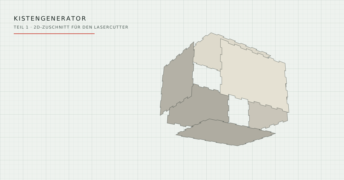
The tool loads only after you click. Open in a separate window ↗
Designing a finger-jointed box is no big deal. Once. The second time, with different dimensions, you start all over again: redistributing the fingers so that they end the same way at both ends, assigning the corners so that no two panels share the same piece of material, and finally calculating out the kerf. None of this is difficult. It is just the same half hour every time.
So I put it into a tool. It runs in the browser, consists of a single HTML file and works without an internet connection. Nothing is uploaded, nothing is stored.
What you get
You enter outside or inside dimensions, choose material thickness and finger width, and get the finished cutting layout as SVG or DXF. In addition, there is a 3D preview with an assembly slider, so that you can see before cutting whether the box looks the way you imagined it.
Three designs are possible:
| Design | Description |
|---|---|
| Closed | six panels, lid permanently finger-jointed |
| Open | without lid, top edges smooth |
| Sliding lid | lid runs in slots in the side walls, front wall correspondingly lower |
Optionally, there are compartments via dividers in both axes, a recessed slot-in base instead of the finger joint, and press-fit bumps for connections without glue.
Quick guide
Basic settings. Millimetres or inches, outside or inside dimensions, design. With inside dimensions, the tool adds twice the material thickness to width and depth, and once or twice to the height depending on the design.
Dimensions. Width X, height Y, depth Z. The axes correspond to the 3D preview; Y is the height.
Material and joint. This is where the actual work lies. The material thickness must be the measured one, not the printed one. With 3 mm poplar plywood, the actual values are often between 2.7 and 3.2 mm, and the error goes directly into every joint. Use a caliper, measure at several points and enter the average.
The finger width is a target, not a fixed value. The tool divides each edge into an odd number of fingers and adjusts the width so that the pattern starts and ends the same way at both ends. As a rule of thumb, I use three to four times the material thickness. Fingers that are too narrow break during assembly; fingers that are too wide look odd on short edges.
Lid and compartments. For the sliding lid, the value “Lid below top edge” defines how far below the top edge of the side walls the lid runs. The dividers are cross-halved with each other and sit with tenons in slots in the walls.
Cutting sheet. Sheet width and part spacing determine the nesting. This is deliberately kept simple: the parts are placed in rows, without area optimisation.
Files. SVG or DXF, either as one sheet with all parts or as a ZIP with one file per part. For DXF, you can also choose whether the contours are written as polylines or as individual lines. Why this matters is explained further below.
Determining the kerf
The laser beam removes material when cutting. Without compensation, every part ends up smaller by this width and every cut-out larger, and the finger joints are permanently too loose. The tool offsets every cutting path by half the kerf width away from the material, so that the finished edge lies at the nominal size.
The value depends on material, thickness and machine. Guessing does not help. This is how I determine it:
- Switch off kerf compensation.
- Cut a square with an edge length of 50 mm from the material that will be used later.
- Measure the cut-out part. It is smaller than 50 mm. The difference is the kerf.
With 3 mm poplar plywood on a 40-watt CO₂ machine, I usually end up between 0.12 and 0.20 mm. Acrylic is lower, thicker plywood higher. The value measured this way is a good starting point; the final check is always a small test box, about 60 × 40 × 50 mm. That costs five minutes and a piece of offcut.
If you want a tighter fit, enter a slightly smaller kerf value; for an easier fit, a larger one. The fit clearance next to it only affects slots and the sliding lid, not the finger joints.
Import into Alibre Design and Atom3D
The output is not only intended for the laser. Both formats can be imported as sketch geometry and then extruded by the material thickness. This gives you a 3D model of the box without drawing a single line yourself.
Two things have to be considered.
First: one part per file. A sheet with all parts ends up in the model as one single sketch, and extruding would pull everything up together. Alibre Design and Atom3D work without multi-body parts, so each panel needs its own document. This is what the single-part output is for: each part in its own file, origin in the lower left corner, all together in a ZIP archive.
Second: individual lines instead of polylines. On DXF import, Alibre treats a POLYLINE as one single connected object that first has to be broken up before you can work with it. For a finger-jointed wall with fifty contour points, this takes noticeably long; with more complex layouts, it becomes unpleasant. That is why there is the setting “Individual lines”: each segment is written as its own LINE object, and breaking up is no longer necessary at all. For laser software, polylines are usually the better choice because the cutting order follows from them. For CAD import, individual lines are.
Incidentally, the finger recess of the sliding lid is output as a real circular arc, as an ARC object in DXF and as an arc segment in SVG. Not a polygon made of sixteen short segments.
The workflow in CAD is then: create a sketch, import a file, extrude by the material thickness, next part.
How the finger joints are built
For those who want to know more. At each of the twelve edges, two panels interlock. The number of fingers per edge is always odd, so that the pattern ends the same way at both ends.
The question of the corners is more interesting. Three panels meet there, and the corner cube can only belong to one of them. I assigned a fixed order of precedence: front and back wall claim every corner, the side walls are set back from them, and base and lid are set back from all the others. That sounds arbitrary, but it is the point at which home-made generators often assign material twice, and the box then does not go together.
The slot-in base has another special feature. A real groove with partial depth cannot be made with the laser; the beam always cuts through. The base therefore works with through slots, and the tenons are visible flush on the outside. If you do not want that, use the finger joint connection.
What it cannot do
The nesting is a simple row packing, not an area optimisation. There is no engraving layer and no labelling of the parts in the output file. The dividers are not interlocked with the base; they stand on it. And the slots for the sliding lid and slot-in base are visible from the outside; this is due to the laser and cannot be designed away.
The press-fit bumps only work with deformable material. Plywood and MDF yes, acrylic and aluminium no; there the interference leads to cracking. How interference and clearance are standardised for metal fits is shown by the ISO 286 tolerance calculator.
Part 2 goes three-dimensional
The geometry core knows no file formats. It delivers contours, and what becomes of them is decided by the consumer. So far, that is a polygon export to SVG and DXF. In the second part, it will be an AlibreScript that creates solids with a feature tree directly from the same contours, instead of building them via the detour of sketch import. A STEP model directly from the browser would also be technically possible; more on that later.
Download
The tool is a single HTML file, around 76 kB, bilingual German and English. It needs neither installation nor registration and transmits no data. Saving it and opening it in the browser is enough, also without an internet connection. © O-Punkt CAD GmbH, all rights reserved. You can reach the download via the button above, below the title image.
A final note, which is unfortunately necessary: the generated files are a design aid. They replace neither the test cut nor the safety instructions of the machine manufacturer. Measure the material thickness, determine the kerf, check the contours and do not leave the laser unattended during operation.