

The drawing says Ø 25 H7/g6. So the hole is made to H7 and the shaft to g6. What follows from that is not stated: how much clearance remains, whether the parts can be assembled by hand and what happens if someone replaces g6 with k6.
The ISO 286 tolerance calculator does this conversion. First the system behind the designation, then the tool.
All values are metric according to ISO 286. Sources using inch dimensions and fit systems according to ANSI B4.1 do not apply here.
How a tolerance designation is read
A tolerance designation consists of three parts:
The nominal size. The theoretical target value, 25 mm in the example. It is never hit exactly but serves as the reference.
The letter. It defines where the permitted deviation lies relative to the nominal size. Capital letters stand for internal features, i.e. holes. Lower-case letters stand for external features, i.e. shafts. This is the most common mix-up: H7 is a hole, h7 is a shaft.
The number. It defines how wide the permitted deviation is. The standard tolerance grade ranges from IT1 to IT18. The smaller the number, the tighter the tolerance and the more demanding the manufacturing.
So Ø 25 H7 means: internal feature, position according to H, width according to IT7.
What the letter does and what the number does
The two are independent of each other, and this is exactly what is often confused.
The letter determines the fundamental deviation, i.e. the distance of the tolerance zone from the zero line. With H, the zone lies entirely above the nominal size, so the hole is never smaller than 25.000 mm. With g, it lies entirely below, so the shaft always remains smaller than 25.000 mm. With p, it lies above, so the shaft is always larger than the nominal size.
The number only determines the width of this zone. At a nominal size of 25 mm, IT7 is 21 µm wide, IT6 only 13 µm. The same width applies to all letters. It also depends on the nominal size: for a size of 400 mm, IT7 is 57 µm, considerably wider than at 25 mm.
This leads to a practical rule: the letter decides the function, the number decides the manufacturing effort.
The three types of fit
Only the pairing of hole and shaft results in a fit. Three cases have to be distinguished:
Clearance fit. The shaft is always smaller than the hole. There is always clearance, regardless of how the individual parts turn out within their tolerance. For bearing points, guides and anything that is meant to move.
Transition fit. Depending on how the parts turn out, there is either some clearance or some interference. For connections that are meant to sit precisely but remain detachable.
Interference fit. The shaft is always larger than the hole. Assembly requires force, heating of the hole or cooling of the shaft. For connections that transmit torque and are not meant to be separated again.
This can be seen from the designation itself without calculation: if the shaft letter lies in the range a to h, an H hole gives clearance. With j to n there is a transition, from p upwards there is interference.
An example with numbers
Nominal size 25 mm, i.e. nominal size range over 18 up to 30 mm. There, IT6 equals 13 µm and IT7 equals 21 µm.
| Tolerance class | Lower deviation | Upper deviation | Limits of size |
|---|---|---|---|
| H7 (hole) | 0 µm | +21 µm | 25.000 / 25.021 mm |
| g6 (shaft) | -20 µm | -7 µm | 24.980 / 24.993 mm |
| h6 (shaft) | -13 µm | 0 µm | 24.987 / 25.000 mm |
| k6 (shaft) | +2 µm | +15 µm | 25.002 / 25.015 mm |
| p6 (shaft) | +22 µm | +35 µm | 25.022 / 25.035 mm |
This gives the following pairings:
| Fit | Result at Ø 25 mm | Type |
|---|---|---|
| H7/g6 | 7 to 41 µm clearance | clearance fit |
| H7/h6 | 0 to 34 µm clearance | borderline case, clearance at least zero |
| H7/k6 | 15 µm interference to 19 µm clearance | transition fit |
| H7/p6 | 1 to 35 µm interference | interference fit |
The fit tolerance, i.e. the span between the least favourable and the most favourable case, is 34 µm in all four cases. This is no coincidence: it is always the sum of the two standard tolerances, here IT7 plus IT6. If you want to reduce the scatter of a fit, you have to change the IT grades, not the letter.
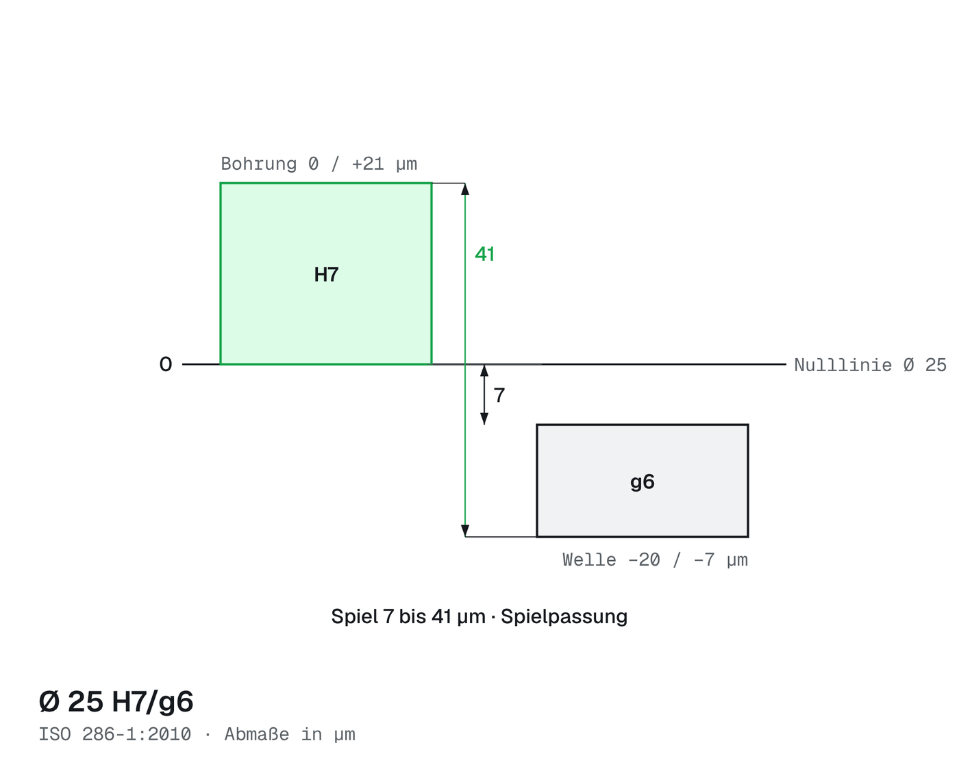
Fit Ø 25 H7/g6: clearance between 7 and 41 µm.
Hole-basis or shaft-basis system
Two routes lead to the same goal:
Hole-basis system. The hole is always made to H, the fit is set via the shaft letter. Recognisable in the drawing by the H on the hole side.
Shaft-basis system. The shaft is always made to h, the fit is set via the hole letter.
In practice, the hole-basis system clearly predominates. The reason lies in manufacturing: holes are produced with fixed-size tools such as reamers, and each tolerance position would need its own tool. A shaft, on the other hand, can be turned or ground to any size without changing the tool.
The shaft-basis system remains useful where drawn bar stock is used without rework, or where several components with different fits sit on one continuous shaft.
Common standard fits and what they stand for
The following thirteen pairings cover most of practice. They are available as a quick selection in the tolerance calculator.
| Fit | Type | Typical use |
|---|---|---|
| H7/g6 | clearance | sliding fit, guided parts with little clearance |
| H7/f7 | clearance | running fit, plain bearings at moderate speed |
| H8/f7 | clearance | running fit with more clearance, non-critical bearing points |
| H8/e8 | clearance | loose running fit, longer bearings, thermal expansion |
| H9/d9 | clearance | coarse running fit, simple applications |
| H11/d11 | clearance | very coarse, unmachined parts, bolted joints without a guiding function |
| H7/h6 | borderline | location fit, can be assembled by hand, without noticeable clearance |
| H7/k6 | transition | firm fit, assembled with light force, detachable |
| H7/m6 | transition | tight firm fit |
| H7/n6 | transition | tight fit, mostly interference |
| H7/p6 | interference | press fit, assembled under force or with a temperature difference |
| H7/r6 | interference | strong press fit |
| H7/s6 | interference | heavy press fit, high torque transmission |
The assignment of uses is a classification for practice, not a requirement of the standard. ISO 286 defines the tolerance values, not their purpose. For load-bearing or safety-relevant connections, the fit is part of the design and has to be calculated, not taken from a table.
What a size tolerance does not cover
A fit according to ISO 286 only says something about the size, not about the shape. A hole can lie exactly within the tolerance zone and still be unusable if it is out of round, tapered or skewed. Separate sets of rules apply to this:
- Geometrical tolerances according to ISO 1101 for roundness, cylindricity, perpendicularity and position.
- Surface roughness according to ISO 21920, the successor to ISO 4287 and ISO 4288. With an interference fit, a rough surface takes up part of the interference, and the effective interference is smaller than calculated.
The general tolerances are also changing. ISO 2768-2, the part with the geometrical tolerances, was withdrawn internationally in 2021 and replaced by ISO 22081; the German adoption is available as DIN EN ISO 22081:2022-10. This standard no longer contains numerical values, which is why DIN 2769:2023-04 was added as a national supplement with tables. The drawing note “ISO 2768-mK” therefore refers, with its K part, to a withdrawn standard. For existing drawings, the entered note remains binding; for new designs, a dated reference or the switch to ISO 22081 with DIN 2769 is the clean solution.
ISO 286 is not affected by this. Individually specified fits take precedence over any general tolerance.
Information as of September 2026. Editions of standards change; check the currently valid edition before binding use.
Frequently asked questions
What does H7/g6 mean?
The hole is made to H7, the shaft to g6. At Ø 25 mm, the hole lies at 0 to +21 µm, the shaft at −20 to −7 µm. There is always a clearance between 7 and 41 µm, so H7/g6 is a clearance fit.
How large is the tolerance H7 at 25 mm?
At a nominal size of 25 mm, the hole H7 lies between 25.000 and 25.021 mm. The lower deviation is 0 µm, the upper +21 µm. The width of 21 µm corresponds to the standard tolerance grade IT7 in the nominal size range over 18 up to 30 mm.
What is the difference between clearance, transition and interference fits?
With a clearance fit, the shaft is always smaller than the hole and there is always clearance. With a transition fit, there is either some clearance or some interference, depending on manufacturing. With an interference fit, the shaft is always larger, and assembly requires force, heating of the hole or cooling of the shaft.
The tool
The ISO 286 tolerance calculator calculates limits of size and deviations according to ISO 286-1:2010. It runs directly in the browser, without installation, and transmits no data. The entire calculation logic, including all tabulated standard values, is contained in a single HTML file (55 KB).
Features
Single tolerance
Enter the nominal size and tolerance class (e.g. Ø 25 H7). The calculator returns:
- Upper and lower deviation in µm and mm
- Maximum and minimum size
- IT tolerance value
- Graphical representation of the tolerance zone
- Detail table with all values
All fundamental deviations for shafts (a–h, j–n, p–zc) and holes (A–H, J–N, P–ZC) are supported, including js/JS (symmetrical) and j (IT5–IT8).
Fit calculator
Enter hole and shaft together (e.g. Ø 25 H7/g6). The calculator determines:
- Type of fit (clearance, transition, interference)
- Maximum and minimum clearance or interference
- Fit tolerance
- Individual values of both partners in comparison
- Fit diagram with both tolerance zones
13 ISO standard fits are available as a quick selection, colour-coded by type of fit.
IT table
Complete overview of all standard tolerances IT1–IT18 for the 13 nominal size ranges from >0 to 500 mm. If a nominal size is also entered, the calculator highlights the corresponding row.
Technical specifications
- Nominal size range: >0 to 500 mm (13 main ranges, 25 sub-ranges)
- IT grades: IT1 to IT18 (complete)
- Fundamental deviations, shaft: a, b, c, cd, d, e, ef, f, fg, g, h, js, j, k, m, n, p, r, s, t, u, v, x, y, z, za, zb, zc
- Fundamental deviations, hole: all corresponding capital letters, with Δ correction for K/M/N
- Languages: German and English, switchable, the language choice is saved
- File size: 55 KB, a single HTML file
- Dependencies: none, works offline in any modern browser
Data quality
The embedded tolerance tables and fundamental deviations were systematically verified against two independent sources:
- DIN ISO 286-2 extract (Ganter standard parts): 290 individual values
- ISO 286-1 reference tables (roymech.org): 543 individual values
Overall result: 881 tests passed, 0 errors.
Known limitations
- Letter j is implemented for IT5–IT8 and is not available outside this range.
- js with an odd IT value: mathematical rounding (deviation of ±0.5 µm possible).
- Holes K/M/N at IT ≥ 9: the calculation is based on an empirically derived rule from ISO 286-2. For safety-critical applications in this range, consult the original standard.
- Rarely used fundamental deviations (cd, ef, fg, v, y) are only implemented for the nominal size ranges in which they are defined in the standard.
Usage
Online, the calculator runs directly on alibre.info: ISO 286 tolerance calculator online. For use without internet, download the file, save it locally and open it in your browser. All calculations run locally. No data is transmitted.