

Anyone modelling a pipe in CAD or building a bill of materials works with three number systems: the nominal size DN, the nominal pressure PN and the actual dimensions outside diameter × wall thickness. These three quantities are regularly confused. This article explains what each one means and which standard governs it.
Requirement for the script: Alibre Design Pro or Expert from V29 (Alibre Script is not included in Atom3D). Compare editions (in German)
Table: DN, inch size, outside diameter and wall thickness
Threadable tubes according to DIN EN 10255, series M and H. e is the wall thickness in mm.
| DN | Inch | Outside Ø (mm) | e (M) | kg/m (M) | e (H) | kg/m (H) |
|---|---|---|---|---|---|---|
| 6 | 1/8" | 10.2 | 2.00 | 0.404 | 2.60 | 0.487 |
| 8 | 1/4" | 13.5 | 2.30 | 0.641 | 2.90 | 0.765 |
| 10 | 3/8" | 17.2 | 2.30 | 0.839 | 2.90 | 1.02 |
| 15 | 1/2" | 21.3 | 2.60 | 1.21 | 3.20 | 1.44 |
| 20 | 3/4" | 26.9 | 2.60 | 1.56 | 3.20 | 1.87 |
| 25 | 1" | 33.7 | 3.20 | 2.41 | 4.00 | 2.93 |
| 32 | 1 1/4" | 42.4 | 3.20 | 3.10 | 4.00 | 3.79 |
| 40 | 1 1/2" | 48.3 | 3.20 | 3.56 | 4.00 | 4.37 |
| 50 | 2" | 60.3 | 3.60 | 5.03 | 4.50 | 6.19 |
| 65 | 2 1/2" | 76.1 | 3.60 | 6.42 | 4.50 | 7.93 |
| 80 | 3" | 88.9 | 4.00 | 8.36 | 5.00 | 10.30 |
| 100 | 4" | 114.3 | 4.50 | 12.20 | 5.40 | 14.50 |
| 125 | 5" | 139.7 | 5.00 | 16.60 | 5.40 | 17.90 |
| 150 | 6" | 165.1 | 5.00 | 19.80 | 5.40 | 21.30 |
Why pipe standards exist at all
Until the late 19th century, every manufacturer made pipes to its own dimensions. Fittings, valves and pipes from different suppliers did not fit together. In the German-speaking countries, standardisation grew from two roots:
The Whitworth pipe thread. The thread dimensions used in gas and water installation date from the age of the steam engine and are still specified in inches today. The outside diameter of such a pipe can be derived neither from the metric nor from the inch system, because the pipes were originally named after their inside diameter and the wall thickness was adjusted over time. A 1/2" pipe has an outside diameter of 21.3 mm. This figure has grown historically; it was not calculated.
The ISO metric thread of bolted joints follows a different system. It is described in the article Metric screws (ISO): head types, standards, property classes.
The DIN dimensional standards. DIN 2440 (medium-weight threadable tubes) and DIN 2441 (heavy threadable tubes) in their last edition of 1978, as well as DIN 2448 and DIN 2458 of 1981, shaped German pipework for decades. All four have been withdrawn and replaced by European standards. The old numbers nevertheless persist in the trade, because they are shorter and clearer to older colleagues.
Nominal size DN: a reference number, not a dimension
DN stands for Diameter Nominal. The quantity is defined in DIN EN ISO 6708:1995-09 “Pipework components – Definition and selection of DN (nominal size)”.
The wording of the standard itself is decisive: DN is an alphanumeric designation used for reference purposes. It is dimensionless and only indirectly related to a physical dimension. DN 20 does not mean an inside diameter of 20 mm, nor an outside diameter of 20 mm.
Example: a threadable tube DN 20 of series M according to DIN EN 10255 has an outside diameter of 26.9 mm and a wall thickness of 2.6 mm, so an inside diameter of 21.7 mm. Here, the nominal size approximately matches the inside diameter. For larger nominal sizes and for pressure-bearing lines with thicker walls, this no longer applies.
The steps follow a preferred number series: DN 6 – 8 – 10 – 15 – 20 – 25 – 32 – 40 – 50 – 65 – 80 – 100 – 125 – 150 – 200 – 250 – 300 and so on.
Anyone dimensioning a drawing therefore never enters “DN 50” as a dimension, but 60.3 × 3.6. DN belongs in the bill of materials and the part name, not in the dimensioning.
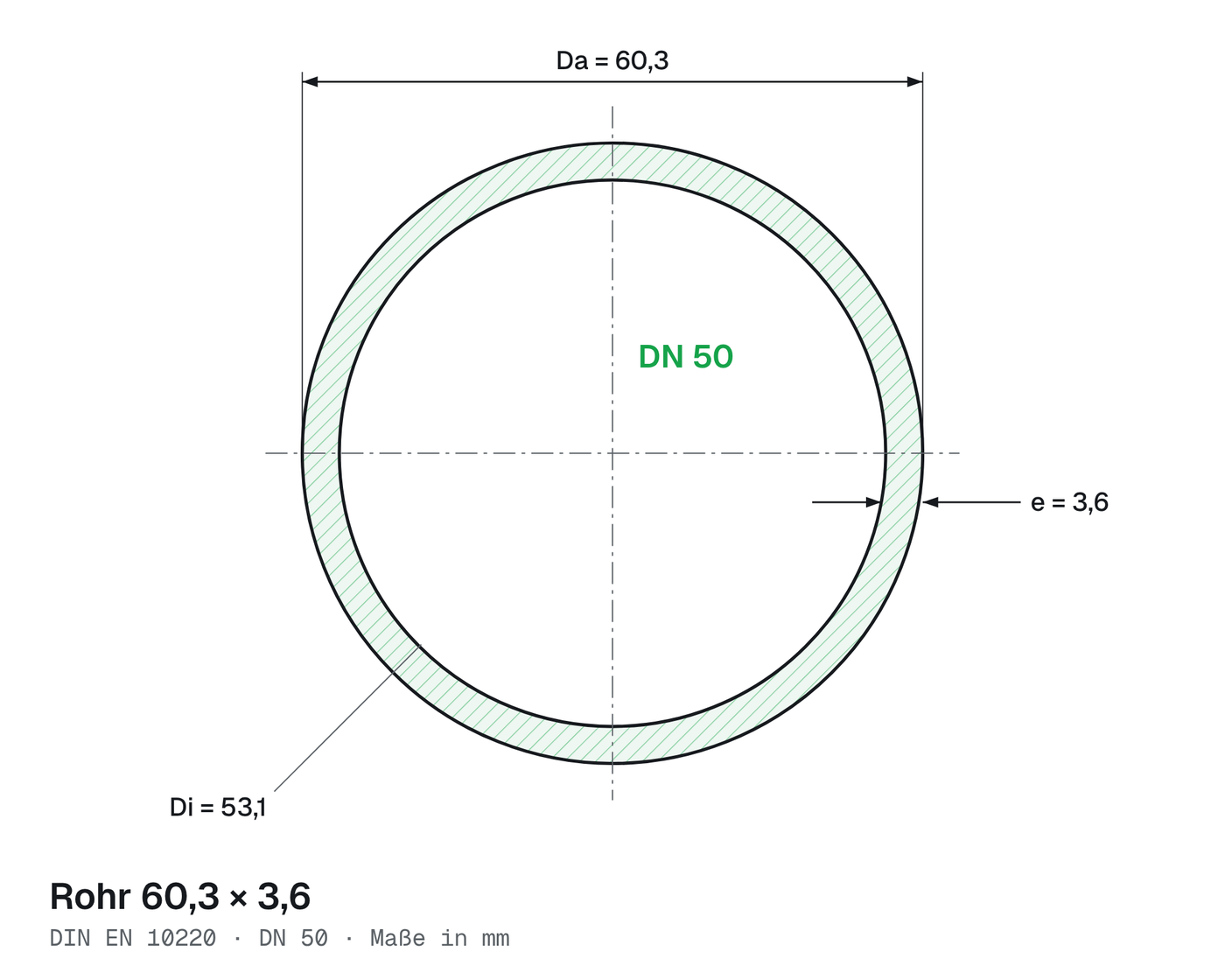
Pipe 60.3 × 3.6 according to DIN EN 10220 (DN 50), dimensions in mm.
Nominal pressure PN: the pressure rating
PN stands for Pressure Nominal and is defined in DIN EN 1333. PN is also a dimensionless reference quantity. It denotes the permissible pressure in bar at a reference temperature of 20 °C.
Standardised steps: PN 2.5 – 6 – 10 – 16 – 25 – 40 – 63 – 100 – 160 – 250 – 320 – 400.
As the temperature rises, the permissible operating pressure decreases depending on the material. PN 16 therefore does not mean that the line still withstands 16 bar at 300 °C. The permissible pressure-temperature combinations are given in the respective component standards, for flanges for example in DIN EN 1092-1.
Older valves still carry “ND 10” for nominal pressure 10 bar. This designation is outdated but can still be found in existing installations.
The combination DN + PN + material makes pipes, flanges, fittings and valves interchangeable across manufacturers. That is the actual purpose of the system.
Threadable tubes: DIN EN 10255
The classic installation pipes of plumbing and heating engineering are governed by DIN EN 10255:2007-07 (“Non-alloy steel tubes suitable for welding and threading”). The standard distinguishes series:
| Series | Colour code | Version | Predecessor standard |
|---|---|---|---|
| L / L1 / L2 | green / white / brown | light ISO series | – |
| M | red | medium | DIN 2440 |
| H | blue | heavy | DIN 2441 |
The dimensions of series M and H are given in the table above.
Caution with tables from the trade
In the transition from DIN 2440 to DIN EN 10255, the wall thicknesses of the medium series changed. DIN 2440 had 2.35 / 2.65 / 3.25 / 3.65 / 4.05 / 4.85 mm, EN 10255 has 2.30 / 2.60 / 3.20 / 3.60 / 4.00 / 5.00 mm. The outside diameters have remained unchanged.
Many product ranges and weight tables in the German-speaking trade still list the old DIN 2440 values today under the heading “according to DIN 2440 / EN 10255”. Anyone building part libraries or mass take-offs from them adopts wall thicknesses that are no longer standardised in that form. The difference is small, but it affects weight calculation, inside diameter and pressure rating verification.
Values apply to plain tubes with plain ends. The wall thickness tolerance is ±10 % for series M, H and L and –8 % for types L1 and L2. The associated pipe thread is standardised in DIN EN 10226 (successor to DIN 2999), galvanising in DIN EN 10240.
General dimension tables: DIN EN 10220
Outside the world of threadable tubes, DIN EN 10220:2003-03 “Seamless and welded steel tubes – Dimensions and masses per unit length” applies. It replaced DIN 2448 and DIN 2458.
The standard specifies preferred dimensions for outside diameter and wall thickness in millimetres, together with the mass per unit length in kg/m for tubes with plain ends. The outside diameters are divided into three series that reflect the availability of accessories: series 1 contains the diameters for which all accessories needed to build piping systems are available. Anyone designing in series 2 or 3 has to check the availability of bends, flanges and valves case by case.
Important for practice: DIN EN 10220 is a purely dimensional standard. It says nothing about material, manufacturing process, scope of testing or permissible pressure. This information is given in the product standards, whose dimension tables in turn are a selection from DIN EN 10220.
The product standards
| Standard | Application |
|---|---|
| DIN EN 10216-1 to -5 | seamless tubes for pressure purposes (non-alloy, elevated temperature, alloy/fine grain, low temperature, stainless) |
| DIN EN 10217-1 to -7 | welded tubes for pressure purposes |
| DIN EN 10255 | threadable tubes, installation engineering |
| DIN EN 10224 | tubes for the conveyance of water (successor to DIN 2460) |
| DIN EN 10312 | welded stainless steel tubes for water lines |
| DIN EN 1057 | seamless copper tubes for water and gas in sanitary and heating applications |
| DIN EN 12735-1 / DIN EN 13348 | copper tubes for refrigeration, air conditioning and medical gases |
| DIN 8074 / DIN 8075 | PE pipes, dimensions and testing |
| DIN EN 12201 / DIN EN 1555 | PE pressure pipe systems for water and gas respectively |
| DIN EN 545 / DIN EN 598 | ductile iron pipes, water and sewage respectively |
| DIN EN 877 | cast iron drain pipes (SML) |
| DIN EN 253 | district heating bonded pipe systems |
Plastic pipes: SDR instead of wall thickness
For plastic pipes, the wall thickness is not specified in absolute terms but via the SDR (Standard Dimension Ratio):
SDR = outside diameter / wall thickness
A smaller SDR means a thicker wall and therefore a higher pressure rating. For PE 100 with water, 20 °C and a safety factor of 1.25 according to DIN 8074: SDR 11 corresponds to PN 16, SDR 17 corresponds to PN 10.
This assignment cannot be transferred. For PE 80 the values are lower, and in gas supply, the German DVGW rules specify their own, considerably more conservative operating pressures: PE 100 with SDR 11 is approved there for 10 bar, with SDR 17 for 4 bar. Material, medium, temperature and safety factor therefore always belong in the specification.
Copper tubes
Copper tubes according to DIN EN 1057 (current edition 2010-06) are designated exclusively by outside diameter × wall thickness. Common installation dimensions are 15 × 1.0, 18 × 1.0, 22 × 1.0, 28 × 1.5, 35 × 1.5, 42 × 1.5 and 54 × 2.0. A DN specification is unusual here and leads to confusion. For drinking water and gas, DVGW approval is also required in Germany.
Wall thickness is the result of a calculation
In plumbing, the wall thickness is chosen from a table. In plant engineering, it is the result of a strength calculation.
The governing standard is DIN EN 13480-3 “Metallic industrial piping – Design and calculation”. For a straight pipe under internal pressure, the core relation is:
e = (p · Da) / (2 · f · z + p)
where
e= required calculated wall thicknessp= calculation pressureDa= outside diameterf= permissible stress of the material at calculation temperaturez= weld joint factor
Allowances are added to this value: corrosion and erosion allowance, allowance for the permissible negative wall thickness tolerance of the delivered tube and, where applicable, allowances for thinning when forming bends. Only then is the value rounded up to the next available wall thickness according to DIN EN 10220.
The legal framework is the Pressure Equipment Directive 2014/68/EU, implemented in Germany by the 14th ProdSV (Product Safety Ordinance). For the scope covered by the directive, calculation according to DIN EN 13480 or alternatively according to the AD 2000 code is a recognised way of meeting the essential safety requirements. Anyone placing piping above the threshold values of the directive on the market bears responsibility as manufacturer for calculation, documentation and conformity assessment. This is not a formality but an obligation with liability consequences. For operation in Germany, the Ordinance on Industrial Safety and Health (BetrSichV) with its inspection obligations also applies.
Sizing by application
The question “which diameter do I need?” is not answered by a dimensional standard, but by the application rules of the respective trade:
Drinking water. DIN EN 806-3 describes a simplified loading unit method in which the pipe inside diameters are determined via tables from the number of draw-off points. Local pressure conditions, geodetic height and minimum flow pressure are not taken into account, and circulation systems are not covered. DIN 1988-300 therefore restricts the scope for Germany: the simplified method may only be used for cold and hot water consumption lines in residential buildings with up to six dwellings, and only if the supply pressure is sufficient and hygiene is ensured. All other installations must be calculated using the detailed method of DIN 1988-300: peak flow, available pressure gradient in hPa/m, individual resistances and permissible flow velocities. Drinking water hygiene sets a limit in the other direction: cross-sections that are too large lead to stagnation and are a planning error, not a safety margin.
Heating. DIN EN 12828 for the design of heating systems, supplemented by VDI 2035 for the prevention of damage caused by scale formation and water-side corrosion.
Gas. DVGW worksheet G 600 (TRGI) for gas installation in buildings, G 260 for gas quality.
Drainage. DIN EN 12056 with the national supplement DIN 1986-100.
Industrial piping. In addition to DIN EN 13480, the operator's rules and industry-specific requirements apply.
Dealing with US specifications
NPS and schedule specifications regularly appear in data sheets, supplier drawings and CAD libraries. Neither is compatible with the DN/PN system, even if it looks that way at first glance.
NPS (Nominal Pipe Size) is the US nominal size in inches according to ASME B36.10M (carbon steel) and ASME B36.19M (stainless steel). NPS 2 roughly corresponds to DN 50. In many sizes, the outside diameters even match, because both systems go back to the same historical inch dimensions.
Schedule is a dimensionless index for the wall thickness, derived approximately from the ratio of operating pressure to permissible stress. Sch 40 is the standard version, Sch 80 the reinforced one. The index does not describe a pressure rating: with the same schedule, the pressure resistance decreases with increasing diameter, because the wall becomes thinner relative to the diameter. A 2" Sch 40 pipe withstands considerably more pressure than a 12" Sch 40.
Class according to ASME B16.5 is not the same as PN. Class 150 lies roughly in the range PN 10 to PN 20, but refers to a different reference temperature and a different characteristic curve. There is no generally valid conversion, only assignment tables in the respective component standards.
Practical consequence: a pipe taken from a US library often fits a European flange geometrically, but is neither designated in conformity with the standard nor verified according to European rules. Anyone adopting such parts checks material, wall thickness and verification again.
Consequences for CAD practice
- Model parametrically by outside diameter and wall thickness, not by DN. DN belongs in the model as an attribute, not in the geometry.
- Keep the part designation complete: tube DIN EN 10220 – 60.3 × 3.6 – DIN EN 10216-1 – P235TR1. Only this chain can be procured.
- Prefer series 1 of DIN EN 10220, unless there is a compelling reason against it. This avoids later procurement problems with accessories.
- Take wall thickness tolerances into account if collisions or fits are critical. The nominal wall thickness is not the minimum wall thickness. Limits of size and fits according to ISO 286 can be determined with the ISO 286 tolerance calculator.
- Version your libraries. Withdrawn standards remain in grown libraries for years. A part library that still references DIN 2448 produces drawings with a standard reference that has not existed since 2003.
Frequently asked questions
What is the outside diameter of a DN 50 pipe?
A threadable tube DN 50 (2") according to DIN EN 10255 has an outside diameter of 60.3 mm. The wall thickness is 3.6 mm in the medium series M and 4.5 mm in the heavy series H. DN is only a reference number, so 60.3 × 3.6 is dimensioned in the drawing.
What is the wall thickness of a DN 20 pipe?
According to DIN EN 10255, a threadable tube DN 20 (3/4") has an outside diameter of 26.9 mm. The wall thickness is 2.6 mm in series M and 3.2 mm in series H, giving 1.56 and 1.87 kg/m respectively. For seamless and welded steel tubes outside the threadable tubes, DIN EN 10220 applies.
What does PN 16 mean?
According to DIN EN 1333, PN 16 denotes a permissible pressure of 16 bar at a reference temperature of 20 °C. As the temperature rises, the permissible operating pressure decreases depending on the material. The pressure-temperature combinations are given in the component standards, for flanges for example in DIN EN 1092-1.
Overview of standards
| Area | Standard |
|---|---|
| Nominal size | DIN EN ISO 6708 |
| Nominal pressure | DIN EN 1333 |
| Dimensions of steel tubes, general | DIN EN 10220 |
| Threadable tubes | DIN EN 10255 |
| Pipe threads | DIN EN 10226 |
| Flanges | DIN EN 1092-1 |
| Calculation of industrial piping | DIN EN 13480-3 |
| Legal framework for pressure equipment | Directive 2014/68/EU, 14th ProdSV, AD 2000, BetrSichV |
| Drinking water sizing | DIN 1988-300, DIN EN 806-3 |
| Heating | DIN EN 12828, VDI 2035 |
| Gas installation | DVGW G 600 (TRGI) |
| Drainage | DIN EN 12056, DIN 1986-100 |
Standards change. Before use in drawings and specifications, check the current edition, for example via the DIN standards portal or your own company's collection of standards.
© 2026 Ralf Schrödter, alibre.info · Alibre Design in Germany by O-Punkt CAD GmbH