
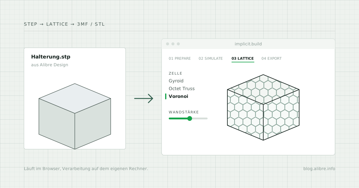
A bracket has been fully designed in Alibre Design and is to be 3D printed. The outer shape is fixed: holes, contact faces and dimensions match the surrounding parts. The inside, however, is solid and costs material, print time and weight. A lattice structure inside would change that, but it can hardly be built in a meaningful way with a B-rep modeller such as Alibre Design.
The browser application IMPLICIT exists for exactly this step. It takes the part as a STEP file, replaces the solid interior with a lattice and delivers a print-ready file for the slicer.
How to reach IMPLICIT
IMPLICIT is not downloaded or installed. The application runs directly in the browser at implicit.build.
- Use a computer with a desktop browser, not a smartphone or tablet: there, only a view without editing is shown.
- Make the browser window wide enough. In a narrow window, the page also shows only the smartphone view.
- No account is needed to get started. Signing in is only required for the Pro and Education plans (see “Prices and plans”).
- On the start page, drag the STEP file into the field or select it via “Choose file”. Five sample parts, including a test cube, are available for trying it out.
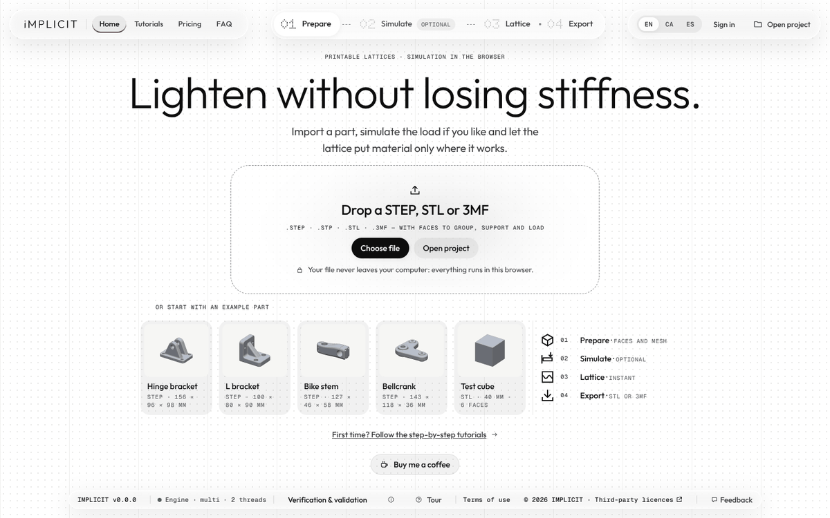
What IMPLICIT is
IMPLICIT is a web application for lattice structures in 3D-printed parts. The outer contour of the part is preserved, the interior is replaced by a network of cells.
Framework conditions according to the provider (as of 23 October 2026):
- Local processing: import, calculation, simulation and export run on your own computer; the part files are not uploaded to a server
- Status: open beta
- Technical basis: geometry kernel PicoGK by LEAP 71 (based on OpenVDB), compiled to WebAssembly; a separate kernel for STEP import
- User interface languages: English, Catalan, Spanish
From the Alibre part to the lattice structure
The workflow is divided into four steps, which are shown as a bar at the top of the application.
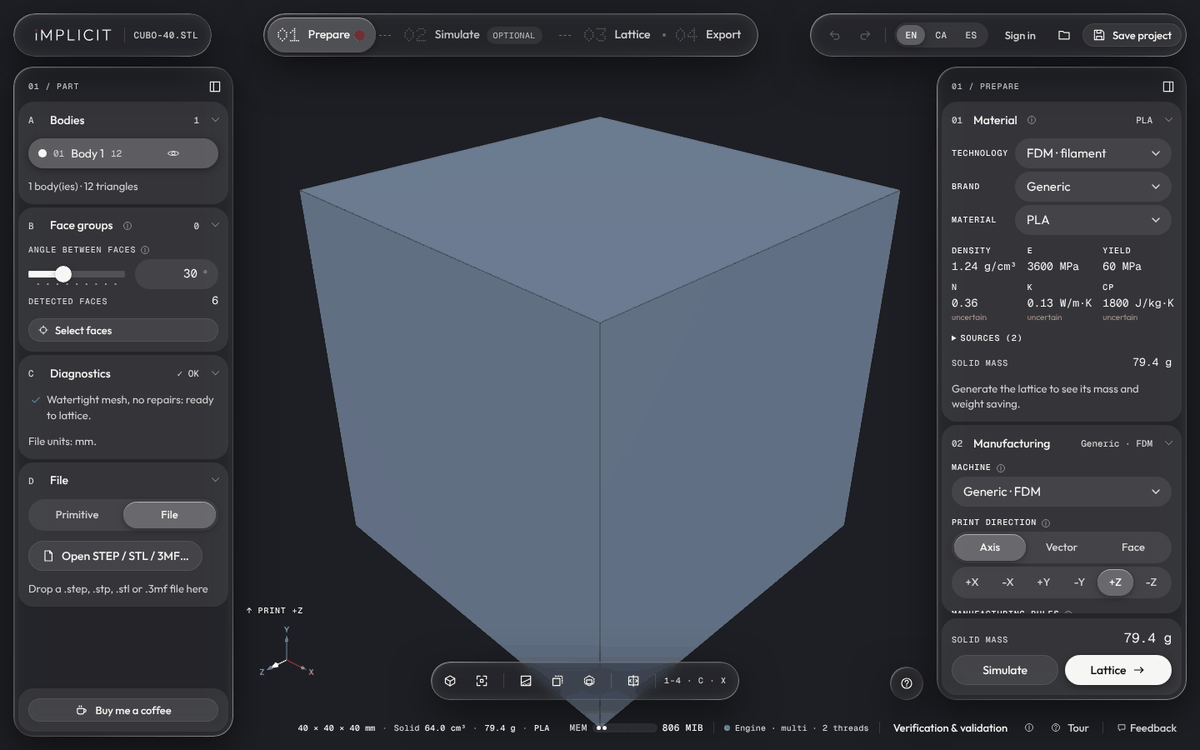
1. Prepare The part is exported from Alibre Design as a STEP file and opened in IMPLICIT. STL and 3MF are accepted as well. Then the material and manufacturing rules are defined:
- Material from a library sorted by technology and manufacturer; density, Young's modulus, Poisson's ratio and yield strength are used for mass and simulation. Custom values are possible.
- Machine with minimum wall thickness, minimum pore size, maximum overhang angle and build direction
- Unit check, in case a file arrives in inches or with the wrong scaling
- Face groups: select and name faces of the part in order to use them later as supports, load application or solid zone
2. Simulate (optional) Supports and loads are placed on the face groups and calculated. The result can later control the density of the lattice.
3. Lattice Lattice type, wall thickness, cell size and outer skin are set. A preview follows every change; the final calculation is preceded by an estimate of memory and time.
4. Export The result is saved as STL or 3MF and goes straight into the slicer. Which export options are available depends on the plan.
Lattice types and grading
IMPLICIT offers three families:
| Family | Variants |
|---|---|
| TPMS (triply periodic minimal surfaces) | Gyroid, Diamond, Schwarz P |
| Strut lattices | BCC, FCC, Octet Truss, Octahedron, Simple Cubic |
| Stochastic | Voronoi (foam and struts), Delaunay, Spinodal (sheet and network) |
Wall thickness or cell size can stay constant across the whole part or be controlled by a field. The field can be a gradient, the distance to the surface, attractors that can be moved freely in the 3D view, or a simulation result (stress or temperature). A mapping curve converts the field value into a wall thickness. This gives the lattice more material where the part is under higher load.
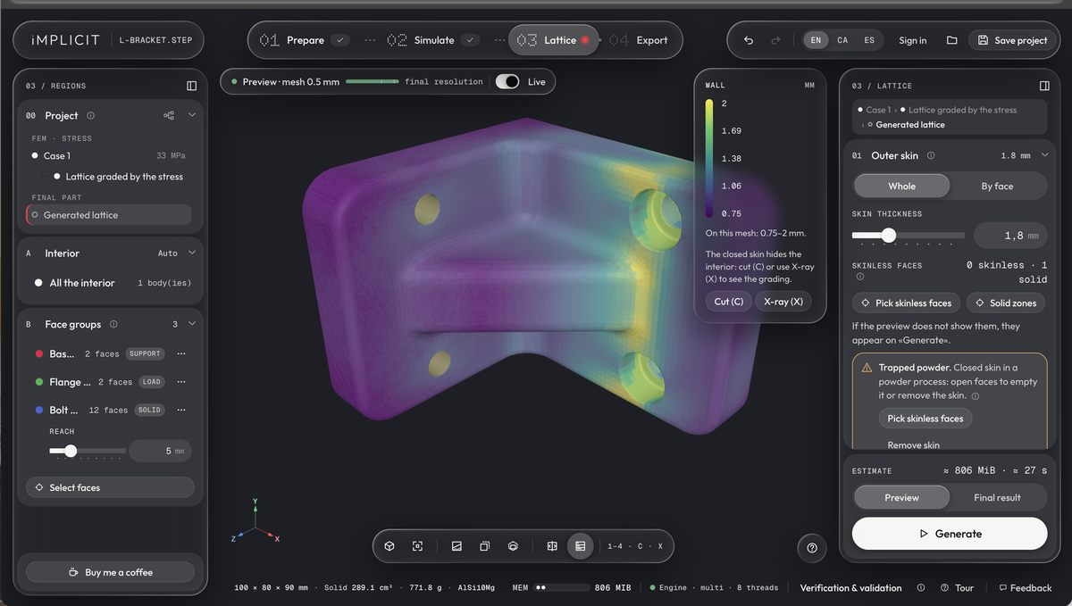
On the sample part L bracket (for the stress calculation see “Simulation and Verify”), the stress controls the wall thickness of the lattice between 0.75 mm (purple) and 2 mm (yellow). The thicker walls are located in the area of the flange transition and the holes. On the right, the application points out that a closed outer skin traps the residual powder in powder bed processes. Open faces or leaving out the outer skin solve this.
Important for practical manufacturing:
- Face groups can be kept solid, for example around holes and contact faces
- Individual faces can stay open (without outer skin), optionally with a frame at the edge
- For Voronoi and Delaunay there is an option for FDM printing without support structures: overhangs are limited to the set angle, and the application reports any remaining overhang faces after generation
Simulation and Verify
The following calculations are available in the browser:
- Static strength analysis (FEA) with von Mises equivalent stress, deformation and safety factor, multiple load cases
- Steady-state heat conduction (FEM)
- Topology optimisation using the SIMP method
- Optimisation of the lattice density to a target mass
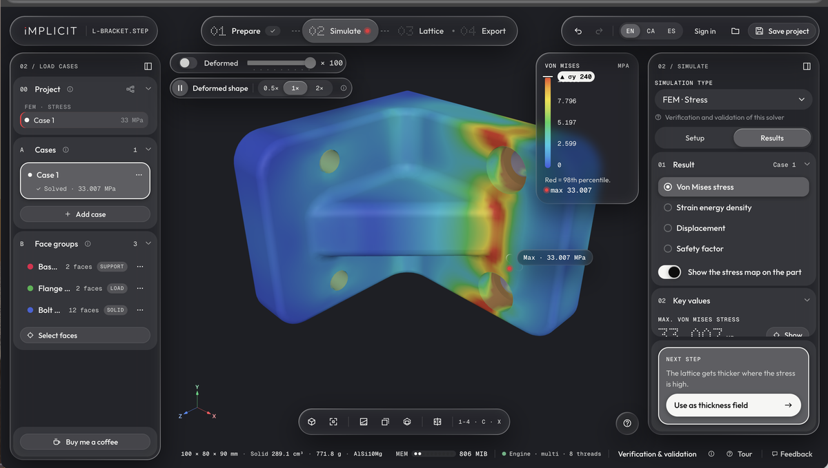
The image shows the application's sample part “L bracket” (100 × 80 × 90 mm, material AlSi10Mg). On the left are the three face groups: base face as support, flange as load application, holes as solid zone. IMPLICIT reports the highest equivalent stress for this load case as 33.0 MPa. Via “Use as thickness field”, the result is taken over directly to control the wall thickness.
The stiffness of the lattice is estimated using a homogenisation model. The provider explicitly describes these values as a starting point for the design, not as proof.
After generation, the Verify step recalculates the load case on the lattice actually generated and compares stresses, deformation and safety factor with the solid part. Verify is part of the Pro plan.
Print checks and export
Before export, IMPLICIT checks the result against the rules of the selected machine: loose parts, minimum wall thickness, pores, overhangs and build volume. Each check returns its own verdict. The export view also shows the weight saving compared with the solid part.
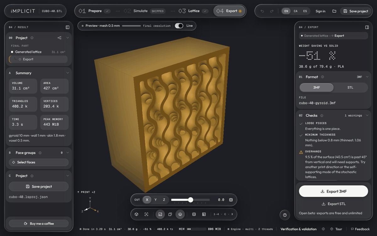
The image shows the application's test cube (40 mm edge length) with a gyroid lattice, cut open via the section plane. For this example, IMPLICIT reports a saving of 51 % compared with the solid PLA cube.
The examples on the website show a steering knuckle, a hub, a robot arm link and a wheel carrier. The provider states weight reductions of between 57 % and 61 % for these. These figures come from implicit.build and have not been recalculated here.
Prices and plans
As of 23 October 2026, according to the pricing page of implicit.build:
| Plan | Price | Scope |
|---|---|---|
| Free | €0 | all tools and simulations, 3 STL exports per day, voxel size from 0.5 mm; no 3MF, no free resolution, no Verify |
| Pro | €12 per month or €96 per year | unlimited exports, 3MF, any resolution, Verify |
| Education | free, 1 year, renewable | same scope as Pro, non-commercial use only (teaching, training, research) |
| Enterprise / Cloud | on request | announced extensions, including cloud calculation of large parts |
During the open beta, all Pro functions are free and nothing is charged. The provider does not give a date for the end of the beta. Payment is handled by the payment service Paddle; prices include taxes. Current prices and terms are on the pricing page of implicit.build.
The interactive tour
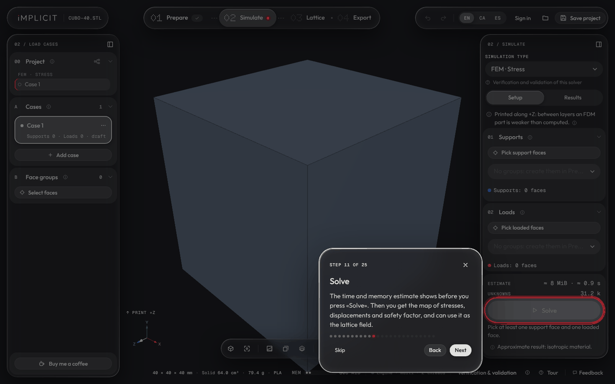
When opened on a desktop for the first time, IMPLICIT offers a guided tour. It leads through the entire interface in 25 steps, from project and language through import, 3D view, material, manufacturing rules, face groups and simulation to lattice types, grading, export, print checks and Verify.
Each step highlights the relevant area of the interface and explains it in a few sentences. You move through it with buttons or arrow keys. The tour can be restarted at any time via “Tour” in the status bar.
Limitations of the application
- Mesh data only in the export: the result is STL or 3MF. There is no way back to Alibre Design as a solid (B-rep). The lattice structure exists only in the export file.
- Memory: in the browser there is a limit of 4 GiB, more in browsers with 64-bit support. Large parts with fine resolution can fail because of this; the application warns before generation.
- Simulation as a design aid: the calculations do not replace a strength verification. According to the terms of use, every part must be checked by the user before manufacture and use.
- Free plan after the beta: 3 STL exports per day, no 3MF and no Verify.
- Language: no German user interface.
- Provider: an individual in Spain; name and address are given in the terms of use. Spanish law applies.
Workflow with Alibre Design
The outer shape is created parametrically in Alibre Design as usual, the lattice structure afterwards in the browser. A STEP file is handed over. Nothing goes back to Alibre; the result goes straight into the slicer.