
A customer sends a bracket as an STL file, downloaded from a 3D printing portal. A part of your own has to be fitted to it: take over the hole pattern, reuse the contact faces, design a mating part. In Alibre Design, there is no body to measure, cut or reference.
The converter “STL to STEP for Alibre” closes this gap. It creates a closed STEP solid from the mesh, which can be opened in Alibre Design and used as a reference. This article describes what it does and what it does not do.
Why STL does not help directly in Alibre
An STL file contains nothing but triangles. The original sketches, dimensions and design steps are gone, even if the part was originally created in a CAD program. A hole in an STL is no longer a hole with a diameter, but a series of narrow triangles approximating a cylinder.
The converter does not change this. It creates a faceted STEP solid, that is, a body made of flat triangular faces. It serves as a modelling reference. No reconstructed parametric CAD file with features and dimensions is produced.
What the converter does
The conversion runs in five steps, each of which can be followed in the tool's log:
- Aligning. The mesh is squared to the axes using its flat faces and centred at the origin. This step can be skipped, in which case the position from the STL is kept.
- Repairing. Small holes are closed, loose fragments removed, and non-manifold edges and vertices split. If the mesh is still not watertight afterwards, nearly coincident vertices within 0.05 mm are welded and the repair is repeated. The triangles are oriented consistently outwards, cavities inwards.
- Decimating. The mesh is simplified with the meshoptimizer library until it meets the tolerance of the selected level within the face limit.
- Checking. Closure, manifoldness, number of shells and volume are checked, and the deviation is measured.
- Writing. The result is saved as STEP AP214 in millimetres.
Binary and ASCII STL files are read.
The conversion runs entirely in the browser. No file is uploaded, and the page loads nothing from the internet. It therefore also works without an internet connection, and design data stays on your own computer. The interface is available in German and English.
How to use it
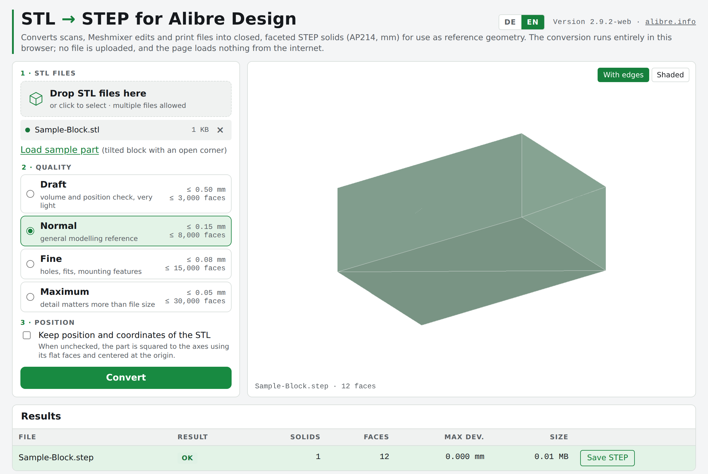
- Open the HTML file in a current browser.
- Drop one or more STL files onto the drop zone or click to select them. Several files are converted one after another. A sample part is included for trying it out (tilted block with an open corner).
- Select the quality level (table below).
- Set the position. With “Keep position and coordinates of the STL” unchecked, the part is squared to the axes using its flat faces and centred at the origin. When checked, the position from the STL remains unchanged, for example when the part has to fit into an existing assembly.
- Click “Convert”. The preview shows the faceted solid either “With edges” or “Shaded”. The results table shows the result, solids, faces, maximum deviation and file size for each file; the log additionally shows the mean deviation and all individual steps.
- Depending on the result, choose “Save STEP” or “Save anyway”. The STEP file takes the name of the STL file.
The four quality levels:
| Level | Max. deviation | Max. faces | Purpose |
|---|---|---|---|
| Draft | 0.50 mm | 3,000 | volume and position check |
| Normal | 0.15 mm | 8,000 | general modelling reference |
| Fine | 0.08 mm | 15,000 | holes, fits, mounting features |
| Maximum | 0.05 mm | 30,000 | detail matters more than file size |
When the mesh is damaged
Not every mesh can be turned into a valid solid by the built-in repair. The file then ends with FAIL, and the tool shows a note pointing to the free online service Formware Online STL Repair. The STL file repaired there can then be converted again.
There is one difference to keep in mind. The converter itself processes all files locally on your own computer. With Formware, the file is uploaded to their server. According to Formware, files are deleted after download, at the latest after six hours. Whether this is permissible for customer data has to be decided case by case.
The check: OK, WARNING, FAIL
Every file receives one of three results.
OK. A closed, manifold solid to which none of the warnings listed below applies. The STEP file is stored with “Save STEP”.
WARNING. The solids are valid and closed, but at least one of the following points applies. The STEP file can still be saved, with “Save anyway”. The log states exactly what applies.
- several separate solids. Bodies that touch only at edges or points cannot be united into one valid solid. They are written as separate solids into one STEP file. Alibre Design opens such a file as an assembly with one part per solid. Bodies that touch face to face are united if both contact faces are meshed identically; otherwise they remain separate solids.
- the maximum deviation exceeds the tolerance of the level, for example because the tolerance could not be reached within the face limit.
- the dimensions of the result differ from the input by more than the larger of two values: twice the tolerance or 1 % of the largest dimension. This indicates that the repair has removed or added geometry.
- the volume differs by more than 3 %. The comparison is made with the original mesh if it was already watertight, otherwise with the repaired mesh.
FAIL. No valid solid was created: the body is not closed, not manifold or has no positive volume. In this case no STEP file is offered.
Important for interpreting the result: the reported deviation is measured against the repaired mesh, not against the original STL. It is measured in both directions, from the result to the repaired mesh and back, at vertices, edge midpoints and face centroids. The maximum deviation is the worst measured point, the mean deviation the typical error across the surface. If the repair has closed a hole or removed a fragment, this change is not reflected in the deviation. It can only show up in the dimension check, and in the volume check only if the original mesh was watertight. The deviation is therefore no substitute for looking at the result.
Technical data
- Version: 2.9.2-web
- Input: STL binary and ASCII, several files per run
- Output: STEP AP214, unit millimetre, faceted solid, cavities are kept
- Processing: entirely local in the browser, a single HTML file without external resources
- Languages: German, English
- File size: according to the tool, the STEP file grows by about 1 MB per 1,000 faces
Known limitations
- No smooth or parametric surfaces. Cylinders, spheres and freeform surfaces remain triangular facets. The result is reference geometry, not production geometry.
- No substitute for checking the repaired shape. The repair closes holes and removes fragments automatically. Whether the result matches the intended shape has to be checked on the model itself.
- Large STEP files with many triangles. Following the rule of thumb above, 30,000 faces at the “Maximum” level result in a STEP file in the order of 30 MB.
- Open surfaces without wall thickness (sheets, shells, single surface patches) cannot be converted into a solid.
Origin and licence
The German edition and the browser application are by Ralf Schrödter, alibre.info / O-Punkt CAD GmbH. It is based on the project stl-to-step-alibre by Mario (mariogt) under the MIT licence.
The meshoptimizer library by Arseny Kapoulkine is embedded for simplifying the meshes, also under the MIT licence. The application itself is licensed under the MIT licence. The full licence texts are in the page source.
The tool is provided free of charge to the Alibre user community. Use is without warranty. Feedback and suggestions for improvement are welcome.
Changes
2.9.2 (27.09.2026) First publication on blog.alibre.info.